 |
| December 17, 2013 | Volume 09 Issue 47 |
Designfax weekly eMagazine

Archives
Partners
Manufacturing Center
Product Spotlight
Modern Applications News
Metalworking Ideas For
Today's Job Shops
Tooling and Production
Strategies for large
metalworking plants
Simulation at work:
Multiphysics systems simulation leads to better understanding of a smaller artificial heart design
By Mark Goodin, CFD Consulting Engineer, SimuTech Group, Cleveland, U.S.A.
and Michael Yaksh, MultiPhysics Consulting Engineer, Lilburn, U.S.A
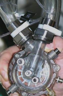
A new continuous-flow total artificial heart (CFTAH) is smaller and less complex than other artificial heart designs. It features a single moving part, the rotor, which is suspended by a combination of magnetic and fluid forces. This new heart is moving into animal testing, which is expensive and time-consuming, so the cost of failure at this stage is high. To minimize the risk and number of expensive design changes, engineering consultants from the SimuTech Group are performing multiphysics simulation that incorporates electromagnetic simulation coupled with fluid flow to fully explore the CFTAH's operation. To date, simulation has been used to calculate the pump's hydraulic performance, static pressures on pump surfaces, rotor torque, rotor axial forces, and other key parameters -- all as part of the process of ensuring product design robustness before testing with live animals.
Potentially life-saving design
More than 300,000 Americans die from heart failure each year, and of these, up to 20 percent die while waiting for a heart donor. Artificial hearts have the potential to save many of these people. But existing FDA-approved devices are complex, bulky, and so large that they fit only 20 percent of women and 50 percent of men.
The CFTAH is a more compact and simpler artificial heart that fits most adults and many teenagers. The device is intended for use as a bridge to a transplant as well as for permanent use to completely replace a failing human heart.
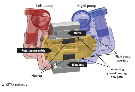
The CFTAH's unique design delivers both simplicity and efficiency. A single motor and single power cable drive the organ's rotating pump assembly. Impellers supporting left and right circulation are mounted on opposing ends of the rotor. The rotor is radially suspended by a blood-lubricated hydrodynamic journal bearing designed to minimize blood shear while maintaining stable operation. During operation, the rotating assembly reaches a radial position in which the fluid-generated hydraulic-bearing forces are balanced by electromagnetic forces exerted by the pump motor.
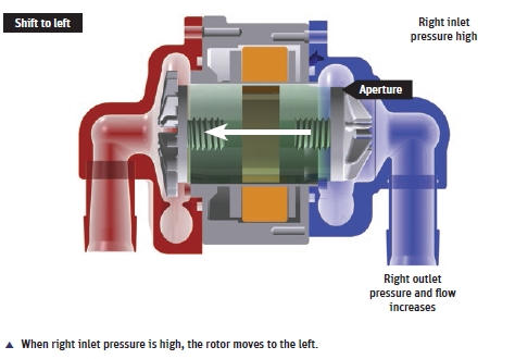
During normal operation, the rotor is free to move axially, and its axial position is determined by the magnet's axial restoring force and opposite-acting left and right pump side pressures. When the right pump pressure is higher than the left pump pressure, the rotating assembly is shifted by hydraulic forces to the left. This leftward shift increases the size of the right pump aperture, which increases the right pump's output pressure and flow rate. The increase in right pump performance raises the pressure and flow rate entering the left pump, which increases the left pump pressure and causes the rotating assembly to shift back rightwards.
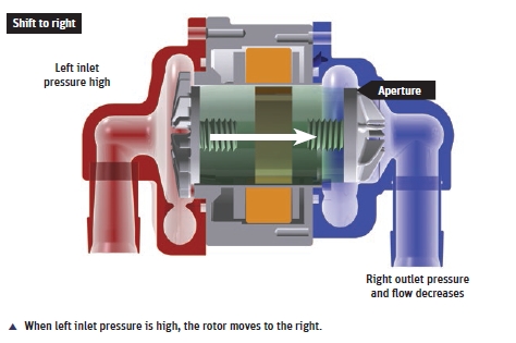
This self-regulation process automatically corrects any imbalances between the right and left side pumps. If there is a sudden change in pump pressure, the motor's axial restoring force limits the overall axial travel of the rotating assembly. This innovative design eliminates the need for components that have complicated other artificial heart designs, such as valves, sensors, and actuation mechanisms.
Role of electromagnetics simulation
Researchers are currently working to validate the CFTAH design in preparation for in-vivo testing in animals. Simulation is needed to capture data that cannot be collected during physical testing as well as to evaluate design alternatives in less time and at a lower cost than could be accomplished with physical testing. Multiphysics simulation was required because of the importance of both electromagnetic forces and fluid flow in determining pump performance. SimuTech engineers began by developing a three-dimensional electromagnetic model in ANSYS software to predict the magnetic radial and axial forces and torques acting on the rotor for different axial and radial offset positions of the rotor with respect to the stator. The final electromagnetic model contained 780,000 hexahedral elements, and the team performed a mesh sensitivity study to validate its accuracy.
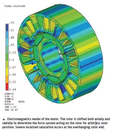
Electromagnetics simulation was used to determine the radial and axial forces generated by the magnet that moves the rotor toward the centerline position as a function of the offset from the center. The design depends on restoring forces to help control and limit the position of the rotor. The simulation showed that the magnet produces a linear radial restoring force of approximately 1,500 Newtons per inch of offset from the centerline of the bearing.
Modeling fluid flow
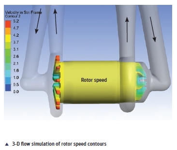
Engineers used the results of the electromagnetic simulation to create a magnetic force table that they incorporated into an ANSYS CFX computational fluid dynamics (CFD) simulation as a user-defined function. The team then used CFD to model the fluid flow through only the journal bearing region of the pump to calculate the rotor radial position at various rotor speeds. As 95 percent of the radial forces are generated in the bearing region, this approach provided accurate positioning results without the need to model the entire pump assembly. Two different hex meshes of the bearing region were used to ensure that the results were independent of mesh density. The finer mesh had 528,000 elements, and the gap between the rotor and housing was 11 elements thick, while the coarser mesh had 216,000 elements and an 8-element-thick gap. The fluid was defined as a water/glycerin mixture with density equal to blood to match the in-vitro test conditions. The model was evaluated at three different rotor speeds.
Deformation of the domain as the rotor moves radially was accomplished by using a moving mesh approach in which displacements relative to the initial mesh were specified with a user-defined function. A diffusion equation representing rotor displacement was included to determine mesh displacements throughout the remaining volume of the mesh. The magnetic restoring forces due to rotor movement were compared with hydraulic forces predicted with CFD to determine the force-balanced rotating assembly position.
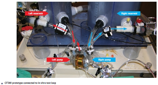
Results match physical testing
For the next step, the team modeled the complete CFTAH pump assembly and compared its performance to physical test results. The full three-dimensional pump model consisted of approximately 15 million elements, including tetrahedral, prism and hexahedral elements. Engineers ran the simulation on a 12-node high-performance computing platform. Due to symmetry and blade clearance in the volute regions, researchers used a frozen-rotor multi-frame-of-reference model and fixed the rotating assembly in one blade orientation -- that is, the flow was modeled under steady-state conditions. They used the same water/glycerin mixture as the fluid and employed the k-omega shear stress transport turbulence model. The model was evaluated at three different volumetric flow rates and three different rotational speeds spanning the intended range of use. Engineers positioned the rotating assembly at the force-balanced radial location calculated earlier and moved the assembly iteratively to an axial location that yielded a right pump outlet pressure matching the in-vitro test data.
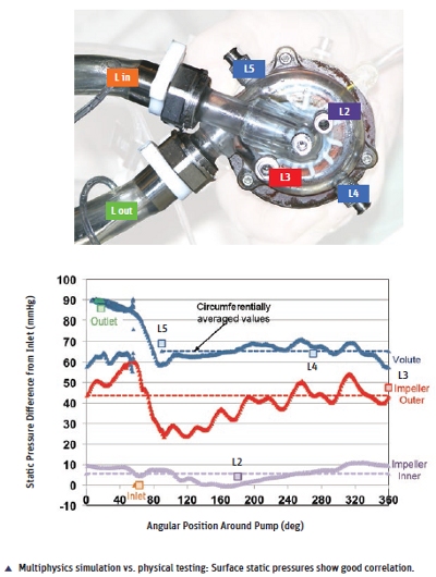
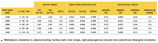
Multiphysics simulations predicted hydraulic performance, surface static pressures throughout the pump, and rotor torque within 5 percent to 10 percent of the prototype's measurements. Radially, the rotating assembly hydraulic forces balanced with the magnetic loads within 5 percent. The axial position of the rotating assembly predicted by simulation matched experimental measurements within 0.25 mm. An axial force imbalance of 0.1 N to 0.5 N toward the left pump was found across the pump's operating range. This force corresponds to a static pressure difference of 2 mm Hg to 6 mm Hg. The reasons for this imbalance will be examined further in future simulations. Overall, these results are quite good and well within the expected level of agreement for this phase of the program.
In a more sophisticated simulation model under development, the team defines the rotor as a moving mesh and uses electromagnetic and hydraulic forces to move the rotor into a force-balanced position during the simulation (instead of setting the initial radial and axial positions). This model will use blood as the fluid, enabling examination of the shear forces exerted on the blood by the pump's surfaces. Shear forces need to be closely controlled; if they are too high, the blood cells may be damaged. On the other hand, if shear forces are too low, the blood may clot. The more-sophisticated simulation model will play an important role in finalizing the design of the CFTAH as it moves into animal testing and toward eventual human use.
Source: ANSYS
Published with permission from ANSYS Advantage Volume VII, Issue 3, 2013.
Published December 2013
Rate this article
View our terms of use and privacy policy